Lemon RX DSMP 10-CH TELEMETRY STABILIZER & VOLTAGE PROBE (DSMX/DSM2 COMPATIBLE)

Contact UsCustomer Reviews

Lemon RX DSMP 10-CH TELEMETRY STABILIZER & VOLTAGE PROBE (DSMX/DSM2 COMPATIBLE)

Our Price:

$52.90


Quantity (4)

Availability 4 in stock
Weight 0.25 lbs
SKU LM-0087VP

Lemon RX DSMP 10-CH TELEMETRY STABILIZER & VOLTAGE PROBE (DSMX/DSM2 COMPATIBLE) 

Product Specifications

Weight and Dimension: 16.3 grams, 66mm x 15mm x 24mm
Recommended voltage range: 3.9V to 8.5V (2S LiPo capable)
Telemetry Option: Integrated with Barometer with Vario, Altimeter, Energy meter (Requires V/I sensor) and Internal Temperature Sensor
Technology: DSMP with GEN2 SDR stack (DSMX / DSM2 compatibility)

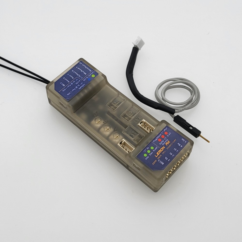
Highlight

The generation 2 DSMP 10-channel telemetry stabilizer is a complete redesign that provides the ultimate reliability, features and performance.

  • Choices of voltage and current sensors with exceptional capability
  •       - XT60 / T-Plug: 5S LiPo (21V max), 60A max.
  •       - Voltage Probe: 45V max.
  • DSMX / DSM2 compatible, 7-channel full-range telemetry stabilizer with full telemetry features including a built-in barometer with vario, altimeter, energy meter (Current, Voltage, mAh),  and internal temperature sensor
  • High sensitivity gyro with proprietary stabilization algorithm ensures responsive airplane control for both electric and gasoline engine application
  • BEC1 and BEC2 dual inputs allow high-reliability operation while improving setup for high current drain performance servo
  • Built-in Detla, V-tail and Normal Wing mixer
  • Supports stabilization with separated channel dual aileron operation
  • Stabilization always-on feature
  • Real-time variable stabilization gain control on channel 8
  • All-channel failsafe
  • Firmware health monitoring software stack and ultra-low operational voltage (3.6V) ensure the highest hardware reliability
  • Generation 2 SDR stack ensures the fastest channel searching and advanced algorithm for signal recovery with ultra-low-latency experience
  • Antenna diversity improves the reliability of the wireless link 
  • Satellite port for additional signal diversity
  • Gyro stabilization activation with either AUX2 or Gear channel
  • 3 potentiometers for individual gain tuning

User manual

- See www.lemon-rx.com/manual

Quick Reference Guide

Reset stabilizer

  • Connect power
  • Hold F and B buttons (approximately 5 secs+) until all LED flashes randomly
  • Press the C button. Multiple LEDs flash a few times to complete the operation

Bind with bind plug

  • Insert bind plug on Channel 7
  • Connect power

Bind without bind plug

  • Connect power
  • Hold the B button until the red LED flashes

Bind with a satellite without a bind plug

  • Connect power
  • Hold the B button until the red LED flashes
  • Disconnect power
  • Plug the satellite wire connector into the stabilizer
  • Connect power

Failsafe

  • Connect power to the receiver and ensure the servos are working with the transmitter
  • Press the F button for 3 seconds until green changes from off to on and vice versa to change the failsafe setting. Channel value is saved as failsafe default at the time the green LED turns on. 
  • Turn off the transmitter and wait 2 seconds to ensure the failsafe is activated accordingly by ensuring there is torque generated with finger-pushing the servo linkage if it was to be set. Vice versa.

Stabilization activation switch

  • Disconnect power
  • Insert bind plug to channel 5
  • Hold the C button
  • Connect power. Wait for about 1 second until the 6 LEDs flash.
  • Release the C button
  • Press C to make changes within 3 seconds. Green = CH7, Blue = CH5.
  • Wait for 3 seconds and remove the bind plug

Wing Mode and Dual Aileron

  • Disconnect power
  • Insert bind plug to channel 6
  • Hold the C button
  • Connect power. Wait for about 1 second until the 6 LEDs flash
  • Check the receiver label/user manual to understand the referred LEDs' operation 
  • Release the C button
  • Observe which red LED is flashing and brief press C to select the required mode
  • Press C to toggle between settings. On means selected. Exit automatically in 5 seconds.
  • Wait for 3 seconds and remove the bind plug
  • Ensure transmitter mixing is set accordingly for dual aileron if stabilized dual aileron is to be configured.

Gyro direction

  • Check the receiver  label/user manual to understand the referred LEDs' operation
  • Connect power and wait 1 second 
  • Hold the C button and wait for about 1 second until the 6 LEDs flash
  • Release the C button
  • Observe which red LED is flashing and brief press C to select the required mode
  • Press C to toggle between settings. On means selected. Exit automatically in 5 seconds.
  • Wait for 3 seconds and remove the bind plug.

V/I sensor calibration

  • Turn on the receiver and transmitter. The telemetry report page may optionally be checked during and after calibration.
  • Plug the V/I sensor. Make sure the required DC loading device such as a brushless motor with ESC as well as the current and voltage meter is connected. 
  • Press the F and B buttons together at the same time for 2 seconds but no greater than 5 seconds
  • Observe 3 green LED flashes. Ensure 8.4V is provided to the V/I sensor.
  • Press F or C button briefly
  • Observe 3 red LED flashes
  • Turn on the DC loading device by throttling the transmitter. Ensure 4A is drawing across the V/I sensor. Be careful with the motor spinning if it is to be used.
  • Press the B button to save and exit.

V/I probe calibration

  • Turn on the receiver and transmitter. The telemetry report page may optionally be checked during and after calibration.
  • Plug the V/I sensor. Make sure the required DC loading device such as a brushless motor with ESC as well as the current and voltage meter is connected. 
  • Press the F and B buttons together at the same time for 2 seconds but no greater than 5 seconds
  • Observe 3 green LED flashes. Ensure 8.4V is provided to the V/I sensor.
  • Press F or C button briefly
  • Observe 3 red LED flashes
  • Press the B button to save and exit.

Gain setting

- Adjust via the 3 dials or real-time master gain on channel 8 depending on the transmitter channel's availability.

View setting LEDs with all on

- Press the C button briefly (no more than 2 seconds).


: *
: *
: *
 

Future Model Red/ White EPP Yak Cowl

Red/ White EPP Yak Replacement Cowl

CW-EPP-YAK-B

$12.00

Booma RC Ignition Switch

Description:

Booma RC

If you want a switch that offers complete dual battery balancing and redundancy with an ultra-small footprint for your scale model then look no further. The new Booma RC intelligent redundant battery balancing switch is the answer.

This switch works with any single or dual battery system. Works with battery chemistry and voltage range from 2.5v to 28v. It comes with a Pin Flag and Ultra Bright Blue LED which can be mounted discretely on your scale model. The Pin Flag controls the internally mounted switch and battery redundancy circuit. The result - beautiful scale appearance with dual battery redundancy peace of mind.

This new balancing technology offers zero voltage drop battery balancing and redundancy which means it can handle huge loads without generating heat. This also means your receiver and servos get all the power unlike conventional battery balancing which loses precious power as heat.

Package Includes:

  • 1 x Pin Flag Switch with mounting hardware.
  • 1 x Ultra Bright Blue LED with mounting hardware.
  • 1 x Dual Battery Balancing power switch circuit.
  • 2 x sets of Input and Output JR connectors.


Specs:


  • Ultra low foot print for the best scale looks.
  • Works with single or dual battery configuration.
  • Works with all battery chemistries. LiFe. LiPo, Lion, NiMh, NiCD. Battery voltage range can be from 2.5volts to 28 volts.
  • Capable of handling input voltages up to 28volts.
  •  Minimal external footprint - All you see on the outside of your model is a 3mm Pin Flag socket and (if required) an ultra-high bright Blue LED. The Pin Flag controls the internal power switch and dual battery redundancy.
  • Full Dual Battery Redundancy - If one battery fails the other battery takes full control.
  •  Maximum Battery Power Balancing - In a dual battery system HS1 draws current proportionally from both batteries while moving both batteries to a complete load balance situation. This means you get the maximum capacity out of both batteries all the time.
  • 2 x 25 amp independent circuits. HS1 is 2 x 25amp circuits into a high power matching battery redundancy circuit. HS1 actually uses 4 x 50 amp rated FET circuits for battery power matching. We passively rate HS1 at 25amps per circuit.

BRC-164-JR

$52.99

Detrum Smart Transmitter 9ch Blitz DT9 with Sr86A-G Autopilot Receiver

Detrum Smart transmitter 9ch Blitz DT9 with Sr86A-G Autopilot Receiver

DY-DM50516

$339.00